이때 보내는 쪽 보드(TX)의 TX와 받는쪽 보드(RX)의 RX와 연결해주고, 보내는보드의 RX핀과 받는보드의 TX와 연결해주어야 시리얼통신이 됩니다.
보내는 보드는 아두이노 나노, 받는 보드는 우노보드를 사용하였습니다.
보내는 측(TX, 나노보드)의 소스코드는
void setup() {
// initialize serial communication at 9600 bits per second:
Serial.begin(115200);
}
// the loop routine runs over and over again forever:
void loop() {
// read the input on analog pin 0:
char msg[] = "Hello World";
// print out the value you read:
Serial.write(msg);
Serial.println();
delay(2); // delay in between reads for stability
}
나노보드의 하드웨어 시리얼핀을 통하여 "Hello World" String을
보내는데 delay(2)를 사용하여 2ms 쉬었다가 한번씩 보내도록 했습니다.
하드웨어 시리얼이므로 baudRate를 115200으로 할 수 있습니다.
배열 char msg[]을 사용하고, Serial.write()함수로 보냈습니다.
char msg[] = "Hello World";
Serial.write(msg);
이번에는 수신보드(RX)인 우노보드에 업로드한 코드입니다.
아두이노 ide에 있는 serialEvent()예제코드에서 loop()문에
Serial.println("OK!");를 추가하였습니다.
이렇게 하면 "OK!"를 시리얼모니터로 출력하면서 동시에 serialEvent()함수로 TX로부터 받은 시리얼값(여기서는 "Hello World")을 출력하게 됩니다.
String inputString = ""; // a String to hold incoming data
bool stringComplete = false; // whether the string is complete
void setup() {
// initialize serial:
Serial.begin(115200);
// reserve 200 bytes for the inputString:
inputString.reserve(200);
}
void loop() {
// print the string when a newline arrives:
Serial.println("OK!");
if (stringComplete) {
Serial.println(inputString);
// clear the string:
inputString = "";
stringComplete = false;
}
}
/*
SerialEvent occurs whenever a new data comes in the hardware serial RX. This
routine is run between each time loop() runs, so using delay inside loop can
delay response. Multiple bytes of data may be available.
*/
void serialEvent() {
while (Serial.available()) {
// get the new byte:
char inChar = (char)Serial.read();
// add it to the inputString:
inputString += inChar;
// if the incoming character is a newline, set a flag so the main loop can
// do something about it:
if (inChar == '\n') {
stringComplete = true;
}
}
}
<출력결과>
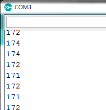
TX측(나노보드)
RX측(우노보드)
RX보드의 loop()문에 있던 "OK!"데이타가 2개 출력될때, TX보드로 부터 받은 "Hello World"데이타가 1개 출력되므로
출력빈도를 1대 1로 맞추려면 TX보드의 출력빈도를 늘려주면 됩니다.
TX보드의 소스코드중 delay타임을 delay(1)로 한 경우 RX보드의 출력데이타가 다음과 같이 깨짐현상이 발생하고,
Hello World 데이타 갯수가 많아 1.5ms로 변경하여 봅니다.
delay(1.5);는 없으므로 delayMicroseconds(1500);으로 변경 후 확인 결과
1개씩 출력하며 1대1로 맞았습니다.
void setup() {
// initialize serial communication at 9600 bits per second:
Serial.begin(115200);
}
// the loop routine runs over and over again forever:
void loop() {
// read the input on analog pin 0:
char msg[] = "Hello World";
// print out the value you read:
Serial.write(msg);
Serial.println();
delayMicroseconds(1500); // delay in between reads for stability
}
마지막으로 TX측 소스코드를 바꾸어 테스트해보면
<소스코드>
void setup() { // initialize serial communication at 9600 bits per second: Serial.begin(115200); }
// the loop routine runs over and over again forever: void loop() { // read the input on analog pin 0: String msg = "Hello World"; // print out the value you read: //Serial.write(msg); Serial.println(msg); delayMicroseconds(1500); // delay in between reads for stability }
배열함수대신 String 변수 msg를 정의하였고, Serial.write(msg)대신 Serial.println(msg) 함수를 사용하였습니다.
결과는 동일하나 OK! 데이타가 간혹 2개씩 출력되는 결과가 보입니다.
코드를 수정하며 TX쪽에서 보내지는 시리얼데이타 전송속도가 달라진다는 것을 짐작할 수 있습니다.
// the setup routine runs once when you press reset: void setup() { // initialize serial communication at 9600 bits per second: Serial.begin(115200); }
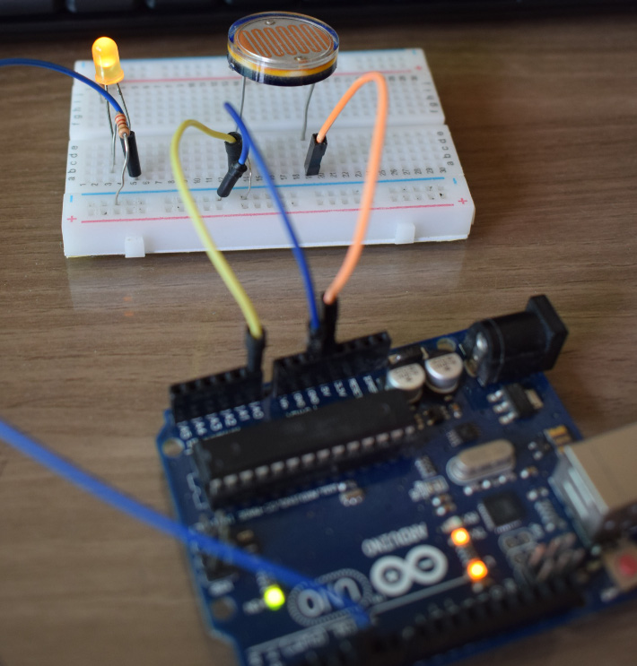
// the loop routine runs over and over again forever: void loop() { // read the input on analog pin 0: int sensorValue = analogRead(A0); // print out the value you read: Serial.println(sensorValue); analogWrite(led, sensorValue); delay(100); }
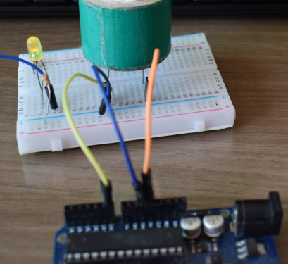
analogRead()를 통해 읽은 sensorValue값을 그대로 analogWrite()의 pwm값으로 사용하였습니다.
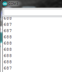
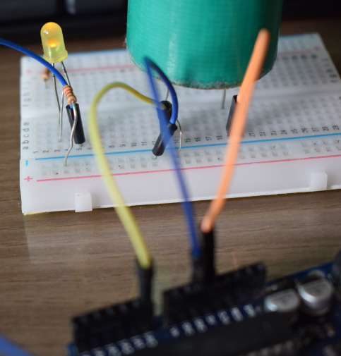
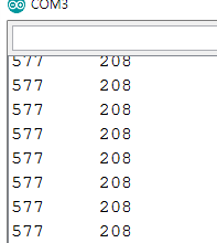
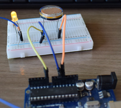
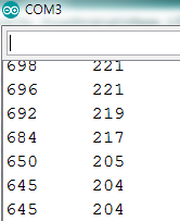
밝은 조건일때
※ 사실 sensorValue = 688은 pwm출력으로 사용하면 문제가 됩니다. pwm출력범위는 0~255입니다
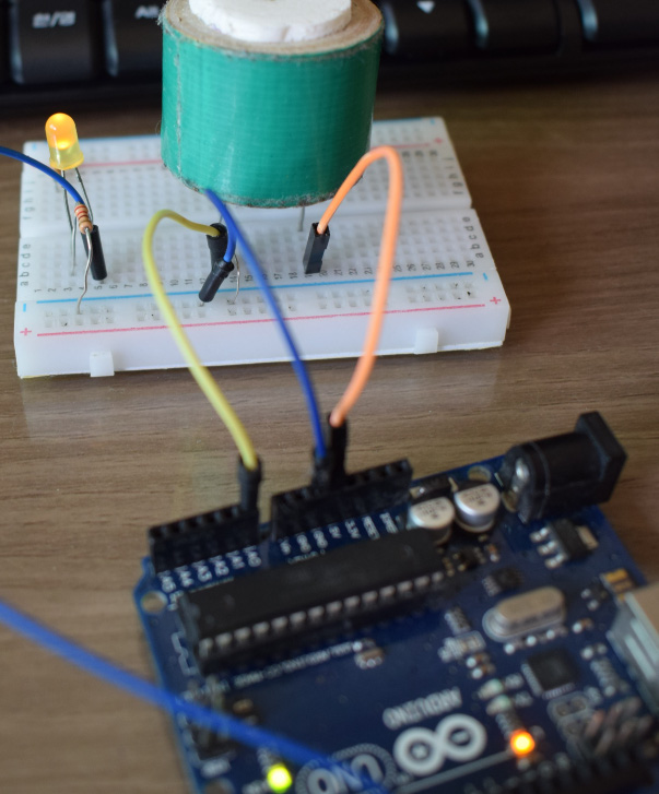
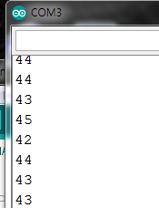
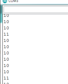
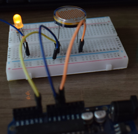
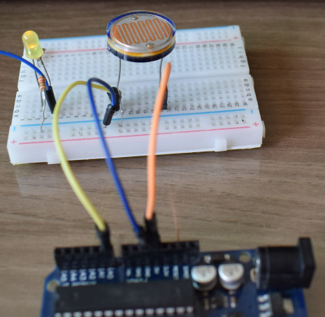
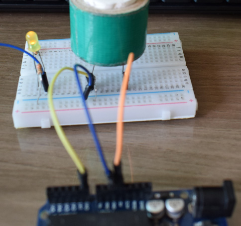
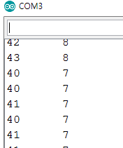
어두운 조건을 만들기 위해 조도센서를 덮었습니다. sensorValue값이 50이하로 떨어졌습니다.
사진상으로는 잘 나오지 않았지만, 밝기가 감소합니다.
좀 더 밝기를 구분해 줄수 있는 방법을 찾아봅니다.
첫번째는 아날로그 입력인 sensorValue 값은 0~1023사이의 범위를 가지는 반면에 pwm출력은 0~255의 범위를 가지기 때문에, sensorValue/4를 하여 pwm출력으로 사용하는 방법입니다.
analogWrite(led, sensorValue/4);
Serial.println(sensorValue/4);
시리얼 모니터 출력도 sensorVlaue/4를 하여 pwm출력값으로 변경하였습니다.
적용결과는
이번에는 조도센서를 가린 경우
앞서의 경우보다 값이 1/4만큼 줄었기 때문에 어두운조건에서 LED 밝기가 약해졌음을 확인할 수 있습니다.
// the setup routine runs once when you press reset: void setup() { // initialize serial communication at 9600 bits per second: Serial.begin(115200); }
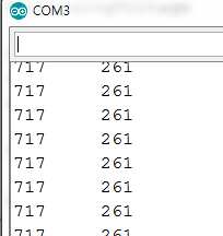
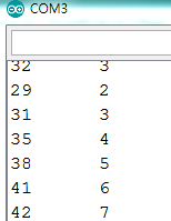
// the loop routine runs over and over again forever: void loop() { // read the input on analog pin 0: int sensorValue = analogRead(A0); Serial.print(sensorValue); // print out the value you read: sensorValue = map(sensorValue, 30,700,0,255); analogWrite(led, sensorValue); Serial.println("\t"+String(sensorValue)); delay(100); }
sensorValue의 범위는 최소 30 ~ 최대 700으로 하였습니다.
pwm출력의 범위는 그대로 0~255로 하였습니다.
map함수는 30 -> 0, 700->255의 범위를 가지도록 매핑시키는 함수입니다.
앞의 값은 조도센서의 sensorValue값이고 뒤의 값은 map()함수를 실행 후의 sensorValue값을 출력합니다.
이런....어두울때의 sensorValue값이 최소범위 30이하로 내려가 마이너스값이 되었습니다.
이때 LED밝기는 전혀 어둡지 않습니다. 밝을때와 차이가 없습니다.
최소값의 범위를 다시 20으로 조정하여
sensorValue = map(sensorValue, 20,700,0,255);
이번에는 최대값이 700을 넘었...
map()함수의 결과도 pwm출력범위 255를 넘어버렸습니다.
밝은조건에서 LED가 어둡네요.
다시 조정합니다.
sensorValue = map(sensorValue, 20,800,0,255);
이번에는 정상적으로 LED의 밝기 구분이 좀 더 확실해졌습니다.
만약 입력값의 최대,최소범위를 좀 더 확실하게 알 수 있다면 출력값의 범위도 좀 더 세밀하게 조정이 가능합니다.
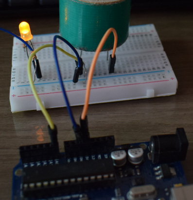
조도센서(CDS)는 빛의 밝기에 따라 저항값이 변하는 일종의 가변저항으로 이해하면 편할것 같습니다.
저항의 한 종류이므로 저항의 전압분배의 법칙을 적용할 수 있습니다.
조도센서는 빛을 받으면 저항값이 작아지고, 어두운 조건에서 빛을 적게받으면 저항값이 커집니다.
위의 그림과 같이 밝기 조건에 대하여 조도센서의 위치에 따라 analogRead의 값이 달라지고, 서로 반대방향으로 움직입니다.
왼쪽 그림과 같이 조도센서가 전원쪽(up side)에 있게되면, 어두운 조건에서 저항값이 커지고, analogRead값은 작아지게 되며, 이것은 전압분배식에서 분모에 위치한 CDS(Ω) 값이 커지면 전체값이 작아지는 것으로 설명됩니다.
반대로, 오른쪽 그림과 같이 조도센서가 GND(down side)쪽에 있게되면, 어두운 조건에서 저항값이 커지고, analogRead값은 커지개 되며, 이것은 역시 오른쪽의 전압분배식에서 CDS(Ω) 값이 커지면서 분자와 분모에 모두 값이 커지지만 분자에 더 영향을 미쳐 전체값이 커지는 것으로 설명됩니다.
아두이노 기본예제인 ReadAnalogVoltage를 활용하여 정확한 전압을 읽는 예제입니다.
/* ReadAnalogVoltage
Reads an analog input on pin 0, converts it to voltage, and prints the result to the Serial Monitor. Graphical representation is available using Serial Plotter (Tools > Serial Plotter menu). Attach the center pin of a potentiometer to pin A0, and the outside pins to +5V and ground.
// the setup routine runs once when you press reset: void setup() { // initialize serial communication at 9600 bits per second: Serial.begin(115200); }
// the loop routine runs over and over again forever: void loop() { // read the input on analog pin 0: int sensorValue = analogRead(A0); // Convert the analog reading (which goes from 0 - 1023) to a voltage (0 - 5V): float voltage = sensorValue * (5.0 / 1023.0); // print out the value you read: Serial.print(sensorValue); Serial.print("\t"); Serial.println(voltage); delay(100); }
아두이노관련 영어어휘를 익히고자 일부러 영문으로 설정하여 사용하여 지금은 한글보다 더 익숙하게 되었습니다.
ide설정을 일부러 영문으로 시작해보는 것도 좋은 방법인 것 같습니다.
/* ReadAnalogVoltage
Reads an analog input on pin 0, converts it to voltage, and prints the result to the Serial Monitor. Graphical representation is available using Serial Plotter (Tools > Serial Plotter menu). Attach the center pin of a potentiometer to pin A0, and the outside pins to +5V and ground.
// the setup routine runs once when you press reset: void setup() { // initialize serial communication at 9600 bits per second: Serial.begin(9600); }
// the loop routine runs over and over again forever: void loop() { // read the input on analog pin 0: int sensorValue = analogRead(A0); // Convert the analog reading (which goes from 0 - 1023) to a voltage (0 - 5V): float voltage = sensorValue * (5.0 / 1023.0); // print out the value you read: Serial.println(voltage); }
아두이노 우노나 나노의 경우 아날로그 입력핀을 10비트로 읽습니다.
2의 10승 = 1024, 하여 0부터 1023까지 1024단계로 읽습니다.
위의 예문 중간부
// Convert the analog reading (which goes from 0 - 1023) to a voltage (0 - 5V):
는 전압 0-5V까지 0-1023의 값으로 읽는다는 의미입니다.
즉 0V -> 0이고, 5V -> 1023에 대응된다면, 5V를 1023등분하면
5V / 1023 = 0.00488 약 0.0049V = 4.9mV
아날로그 입력핀으로 읽는 값은 4.9mV 단위로 구분되어 읽을수 있게 됩니다(해상력이 4.9mV라고 할수 있음)
예를 들어 읽은 값이 value = 758 이라고 했을때 몇 V인지 계산한다면
758 x 0.0049 = 3.7142V 이고
비례식 5V : 1023 = x : 758
x = 758 x 5V/1023 = 3.7047V (0.00488과 0.0049에 의한 오차)
위의 예제 코드중 float voltage = sensorValue * (5.0 / 1023.0); 은
x 를 구하는 전압 float voltage, 758 을 아날로그 입력값 sensorValue로 바꾸면 동일한 식입니다.